Auto Repair Shop In Plainfield, IL

Choosing the right 1/2.5 Inch Scanning Lens starts with the sensor, not the product label. The “1/2.5-inch” format is an optical designation; it does not mean the sensor measures 0.4 inches diagonally. Check the sensor’s active dimensions and confirm that the lens image circle covers them. Otherwise, corners may darken or lose detail.
The application matters just as much. A label inspection line may need a wide field of view, while reading fine marks on a small component demands more resolving power. Record the working distance, object size, required field of view, and smallest feature to detect. Then compare focal length, distortion, aperture, and modulation transfer function (MTF). A larger aperture can help in dim conditions, but it may reduce depth of field. Small trade-offs add up.
The market is growing, but that does not make every lens suitable. MarketsandMarkets’ Machine Vision Market report projected growth from USD 12.6 billion in 2023 to USD 20.6 billion by 2028. That forecast signals expanding use, not a universal optical specification. For practical selection, test the lens with the intended camera, lighting, and target material. Look closely at the image edges. Check focus across the full field. Even a datasheet cannot reveal every installation problem. This guide explains how to compare key specifications, avoid common mismatches, and choose a 1/2.5 Inch Scanning Lens with evidence rather than guesswork. The choice can still be imperfect; documenting test results makes the next decision better.
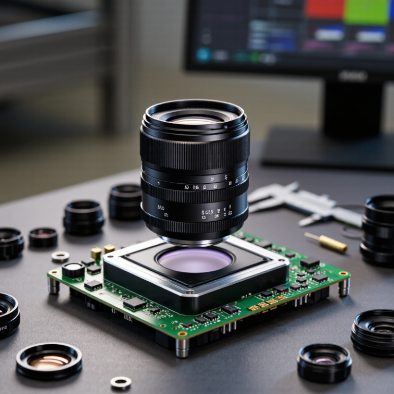
The “1/2.5-inch” label describes a nominal sensor format, not a literal 0.4-inch diagonal. It comes from older imaging conventions, so the sensor’s actual active area can vary slightly between cameras. Check the camera specification sheet for sensor width and height. Those measurements matter more than the label alone.
Coverage is the key match. The lens must project a usable image circle across the sensor, including its corners. A lens rated for a smaller format may produce dark corners or visible vignetting on a 1/2.5-inch sensor. A larger-format lens will often cover it, but the field of view still depends on focal length and sensor size. Small differences count.
For a scanning setup, also compare resolution, working distance, and distortion. A sensor with small pixels needs a lens that resolves fine detail; otherwise, printed edges may look soft even when focus seems correct. Test at the real scan distance. A ruler or fine grid across the frame can reveal blur and edge distortion quickly. Do not trust a tidy specification table alone. I once assumed a format match meant corner-to-corner clarity; it did not. Check the mounted camera under your actual lighting and focus conditions.
| Selection Dimension | What It Means | Practical Guidance | Example or Check |
|---|---|---|---|
| Sensor format | “1/2.5 inch” is an optical-format designation, not the sensor’s literal diagonal measurement. The active dimensions vary between sensors. | Check the sensor datasheet for its active width, height, and diagonal. Select a lens image circle that covers the sensor without corner darkening. | A common 1/2.5-inch sensor size is approximately 5.76 × 4.29 mm, with a diagonal of about 7.18 mm. Confirm the actual sensor dimensions before ordering. |
| Field of view and focal length | Focal length and sensor size determine the angle of view. A longer focal length gives a narrower view from the same camera position. | Choose focal length based on the required field of view and camera-to-subject distance. For a fixed sensor width, horizontal field of view is approximately 2 × arctan(sensor width ÷ 2 × focal length). | With a 5.76 mm-wide sensor, an 8 mm lens gives a horizontal field of view of about 40°; a 12 mm lens gives about 27°. These are approximate values. |
| Working distance and coverage | Working distance is the distance from the lens to the target. Coverage is the width and height of the target visible in the image. | Measure the required target area at the intended working distance, then verify the lens’s field of view with the sensor dimensions. Allow for mounting and focus adjustment. | Do not select a lens from working distance alone: the sensor size and focal length also affect how much of the target is captured. |
| Resolution and pixel size | The sensor’s pixel count and pixel pitch set the sampling detail. The lens must resolve enough detail across the image, including near the edges. | Compare lens resolving performance with the sensor’s pixel pitch and the smallest feature that must be detected. Review resolution or modulation-transfer information when available. | Pixel pitch in micrometres can be estimated as sensor active width in millimetres ÷ pixel count across the width × 1,000. |
| Aperture and depth of field | The aperture affects the amount of light reaching the sensor and the range of object distances that appear acceptably sharp. | Use a wider aperture when light is limited, but check depth of field and image quality. Stopping down can increase depth of field, although very small apertures can reduce sharpness through diffraction. | Test focus across the full depth of the target and at the actual working aperture and illumination level. |
| Mount and mechanical clearance | The lens mount, barrel dimensions, and back-focus arrangement determine whether the lens can be attached and positioned correctly. | Confirm mount type, flange or back-focus requirements, lens diameter, filter thread, and clearance from the camera housing before purchase. | Matching the sensor format does not guarantee that the lens mount or mechanical dimensions will fit the camera. |
| Distortion and edge performance | Distortion changes the apparent shape or position of objects; edge softness or vignetting can reduce measurement reliability. | For inspection or measurement, check distortion correction requirements and evaluate sharpness and illumination across the entire sensor area. | Capture a grid or calibration target at the intended focus, aperture, and working distance to assess image geometry and corner quality. |
| Lighting and spectral response | Image quality depends on the light source, exposure, and the wavelengths transmitted by the lens and detected by the sensor. | Match the lens and any filters to the camera’s sensor response and the illumination wavelength. Check whether infrared-cut or other filtering is needed. | Evaluate the complete camera, lens, filter, and lighting setup rather than the lens in isolation. |
Selection tip: Start with the sensor’s exact active dimensions and required target coverage. Then verify focal length, image-circle coverage, resolution, focus range, mount compatibility, and performance under the intended lighting conditions.
